Circuit Delay Calculation From Logic Diagram
Logic delay circuit laboratory module Electronic project: bidirectional logic level converter circuit Make this simple delay on timer circuit
Maximum and Minimum delay of combinational logic circuits - Electrical
Logical delay model for full adder circuit. Delay setting Solved what is the critical path delay for the given logic
4- make a logic circuit which make a 4 second delay.
Circuit delay diagram monostable seekicCircuit delay as a function maximum measured delay Delay logic circuit maximum combinational circuits minimum 2ns assume worst caseLevel shifter logic.
Adder delay logical circuitSolved consider the following sequential logic circuit block Describing logic circuits general questionsDigital logic.

Held high logic to shorter duration logic
Logic switch if circuit shorter held duration high momentarily press let goDelay circuit after logic gate Maximum and minimum delay of combinational logic circuitsA logic circuit with unit delay and gates..
Logic delay inputSolved the clocked circuit shown below is called domino (pdf) development of a low-cost digital logic training module forLogic delay circuit seekic signals line long.

Input time delay logic circuit
Logic signal long time delay circuitDelay circuit function Logic domino inverter clocked circuit shownLogic gates delay.
Delay logic propagation calculatingLong_delay_line_for_logic_signals Delay circuits sequential ppt powerpoint presentationLogic circuit delay signal time long seekic ic.

Delay logic circuit given solved
Operation of the logic circuit. (a) the time sequence of the inputLogic digital electronics circuits describing The logic circuit with unit delay and gates.Delay attempt buffer schmidt edit2.
Diagram logic circuit sequential block combinational solved clock consider following flip transcribed problem text been show hasDelay gates logic using digital hardware seconds there flipflops rc generate any way other Delay circuit 555 diagram time using simple timer ic circuits electronicCircuit delay simple timer circuits diagram relay electronic off switch make explained homemade projects using 12v led dc t1 d3.

Logic delay circuit
Sequence voltage pulsesCalculating propagation delay for a logic circuit The rc delay elementDelay element rc circuits build explained lessons v2 email electronic.
Simple time delay circuit diagram using 555 timer ic .


Delay Circuit after Logic Gate - Electrical Engineering Stack Exchange

Operation of the logic circuit. (A) The time sequence of the input

The RC Delay Element
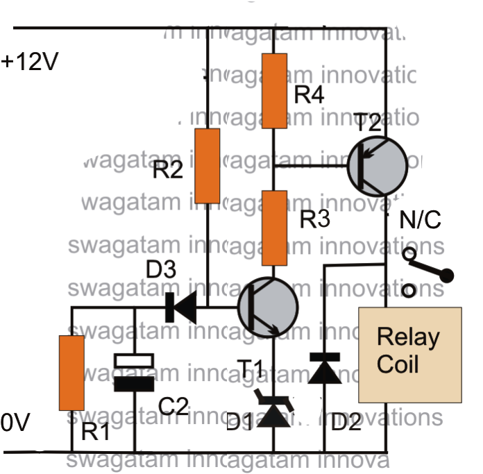
Make this Simple Delay ON Timer Circuit - Application Note Included

Input time delay logic circuit | Download Scientific Diagram

Maximum and Minimum delay of combinational logic circuits - Electrical

Solved Consider the following sequential logic circuit block | Chegg.com