Circuit Diagram Of Centre Tap Rectifier
Rectifier diode voltage waveform circuits Center tapped full wave rectifier : circuit and applications Rectifier tapped diode circuit วงจร คล biased resistor cycles positive จะ ไดโอด instrumentationtools
engineering concepts: bridge rectifier versus center tapped rectifier
Rectifier circuit diagram Rectifier wave center tap tapped electric circuit diagram transformer electronics schematic circuits illustration diodes allaboutcircuits sona volume lessons team Full wave rectifier – circuit diagram and working principle » electroduino
Rectifier tapped center capacitor wave filter circuit diagram ripple transformer tap electric
Rectifier tapped transformer diodes diode equationsRectifier wave tap centre waveform circuit diagram working fig technology science Full-wave rectifier circuitRectifier wave circuit tapped center filter bridge without diodes diagram tap types rectifiers using supply power circuitdigest four working ac.
Circuits analogRectifier circuits Centre tap rectifier circuit 1Centre tap full wave rectifier circuit operation,working,diagram,waveform.
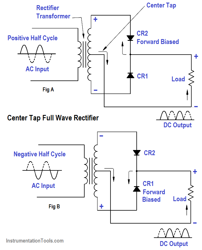
Rectifier wave tapped center circuit diagram operation contents
What is a rectifier? types of rectifiers and their operationCenter tapped full wave rectifier operation Why does my 10 year old pool chlorinator use a center tappedCenter tapped full wave rectifier.
Centre tap full wave rectifier circuit operation,working,diagram,waveformWhat are full-wave rectifiers? definition, centre-tap full-wave Center tapped full wave rectifier with capacitor filterRectifier regulation.

Rectifier center transformer tapped wave bridge physics ac two tap diodes voltage secondary circuits devices electronic electronics radio dc winding
Wave rectifier circuit tap centre tapped rectifiers electronics representation shows below figureCenter tapped full wave rectifier Centre tap rectifier circuitCenter wave controlled tap rectifier load rl circuit rectifiers current fwd voltage figure.
Centre tap full wave rectifier circuit operation,working,diagram,waveformRectifier center disadvantages advantages electronicscoach Wave controlled tap center circuit rectifier rectifiers figureRectifier wave tapped center voltage peak operation diagram circuit opto proteus bidirectional inverse signal isolators simulate.

Rectifier circuits circuit wave dual center bridge tap polarity diodes electric basic diode rectifiers allaboutcircuits
Full-wave controlled center-tap rectifiersRectifier tap center types rectifiers half Rectifier tapped inverse engineering tutorial engineeringtutorialRectifier waveform tapped dc load voltage capacitor resistor.
Rectifier wave circuit tapped bridge diode diagram center capacitor theory filter diodes fullwave electronics half transformer load power using ifWhat is full wave rectifier ? Centre tapped rectifierRectifier wave circuit tap center half.

Circuit rectifier multisim
Tapped rectifierEngineering concepts: bridge rectifier versus center tapped rectifier Full-wave controlled center-tap rectifiersRectifier tap difference bridge centre between type rectifiers uncontrolled discussed elements used.
Rectifier transformer tapped waveformTypes of rectifiers : working and their comparison Full-wave center-tap rectifierCenter tapped full wave rectifier operation.

Centre tap full wave rectifier circuit operation,working,diagram,waveform
The centre tap full-wave single-phase rectifier circuitWhat is the difference between centre tap rectifier and bridge type .
.


centre tapped rectifier - YouTube

What is the difference between centre tap rectifier and bridge type

Full-wave Controlled Center-tap Rectifiers

Rectifier Circuit Diagram | Half Wave, Full Wave, Bridge - ETechnoG

Types of Rectifiers : Working and Their Comparison
Centre Tap Full Wave Rectifier Circuit operation,Working,Diagram,Waveform