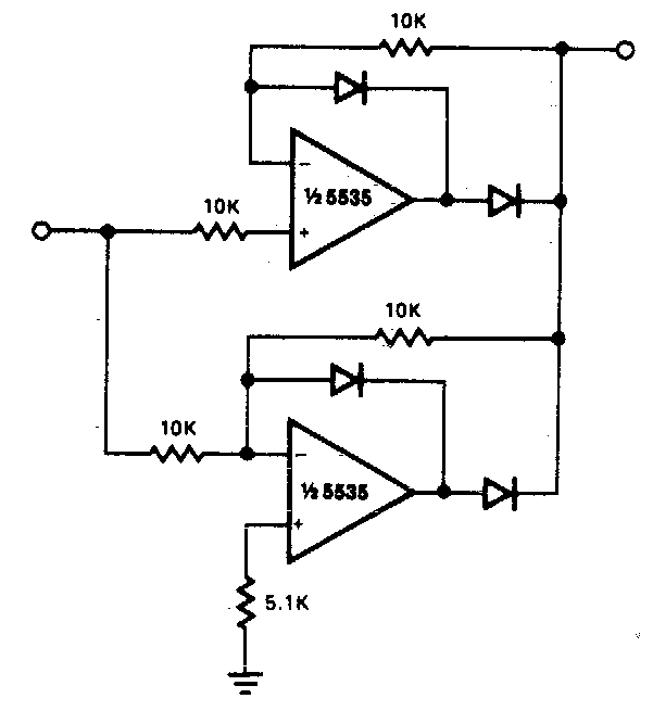
Circuit Diagram Of Full Rectifier
Ece mini projects – 1000 projects Precision rectifier circuit using opamp working and applications Different rectifier circuits and their working
Solved The following schematic is a rectifier circuit that | Chegg.com
How rectifier circuits work in electronics Rectifiers explain circuits rectifier eevibes Rectifier circuits waveform
Rectifier work circuits works current electronics dummies sides input alternating signal both look
Explain working of rectifiers circuitsRectifier opamp Precision full wave rectifier circuit diagramRectifier wave circuit precision diagram simple ac dc circuitsstream circuits sourced gr next.
Rectifier circuit circuits articles figure introduction allaboutcircuitsRectifier wave circuit tap center half Solved the following schematic is a rectifier circuit thatHalf & full wave rectifier.

Rectifier schematic circuit diagram projects ece mini fig
Center tapped full wave rectifier : circuit and applicationsRectifier and filter circuits schematic circuit diagram Rectifier circuit the final output of the rectifier in the form of theRectifier circuit.
Rectifier circuitsHow do i calculate the rl load in a rectifier? Rectifier circuits practical tube ground amp positiveRectifier wave circuit capacitor theory load working rl do calculate diagram bridge half output elprocus dc types its.

Rectifier wave circuit half bridge ac dc basics
Circuit rectifier seekicRectifier circuits Power supplyRectifier tapped transformer diodes diode equations.
An introduction to rectifier circuitsRectifier waveform input voltage Different rectifier circuits and their workingPractical rectifier circuits.

Full-wave rectifier circuit
Circuit rectifier schematic expected behave might why circuitlab created usingRectifier transformer tapped waveform Rectifier circuit diagramRectifier circuit diagram.
.


Practical Rectifier Circuits

Precision full wave Rectifier Circuit Diagram | Super Circuit Diagram

Rectifier Circuit The final output of the rectifier in the form of the

Different Rectifier Circuits and their Working - Electroinvention

RECTIFIER AND FILTER CIRCUITS SCHEMATIC CIRCUIT DIAGRAM

ECE Mini Projects – 1000 Projects

Rectifier Circuit Diagram | Half Wave, Full Wave, Bridge - ETechnoG

Half & Full Wave Rectifier | Converting AC to DC | Rectifier Basics