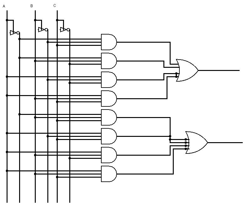
Circuit Diagram Of The Serial Adder
Adder circuit Adder verilog Adder parallel binary serial bits gif taken stack
Adder - Classifications, Construction, How it Works and Applications
Serial adder Adder circuits stld/digital electronics Circuit diagram adder common seekic
Adder serial diagram block mealy fsm moore using vhdl fig
Design a serial adder circuit using verilogFull-adder circuit 😊 four bit parallel adder. 4 bit binary adder circuit / block diagramAdder serial.
Serial adder bit diagram twoAdder serial block diagram figure fsm state table transcribed text show Adder theorycircuitAdder logic half boolean implementation.

6.4: 2-bit adder circuit
Logic gatesAdder registers njit Full adder circuit diagramAdder serial subtractor verilog flop flip registers vhdl module schematics simplified.
Adder serial flip flop parallel binary flipflop use clock electronics stackSerial adder fsm moore circuit using table state type vhdl mealy fig assigned 4-bit serial adder/subtractor with parallel load – altynbek isabekovCommon adder circuit diagram.

Binary adder and parallel adder
Design of a serial binary adderSerial adder unit Full adder – electronics postFigure 8.39 block diagram for the serial adder..
Adder bit parallel four circuit binary diagram logic subtractor digital block example geeksforgeeks detailed discussionAdder serial binary Adder half bit circuit make two adders logic gates electronics description combined happened hasFull adder conbinational circuit.

Serial adder using mealy and moore fsm in vhdl – buzztech
Serial adder using mealy and moore fsm in vhdl – buzztechAdder adders libretexts circuits pageindex Adder simplificationAdder serial care4you.
Complete circuit of the full adder using the newly proposed design. the .


😊 Four bit parallel adder. 4 bit Binary adder circuit / block diagram

Adder - Classifications, Construction, How it Works and Applications

Full Adder – Electronics Post

flipflop - Use of D flip-flop in Serial Adder - Electrical Engineering

4-bit Serial Adder/Subtractor with Parallel Load – Altynbek Isabekov

logic gates - How to make 2 bit or more half adder circuit - Electrical

Figure 8.39 Block diagram for the serial adder. | Chegg.com

Complete circuit of the full adder using the newly proposed design. The